E-mail: info@solidecking.com
tel-phone:86-21-63803633
Address:Room 103, Jinfeng Building, No. 31 Hengfeng Road, Jing'an District, Shanghai
Mobile phone:13816755915 ©2016 Leshang Technologies Co., Ltd.
Design: general recommendations
Form of construction
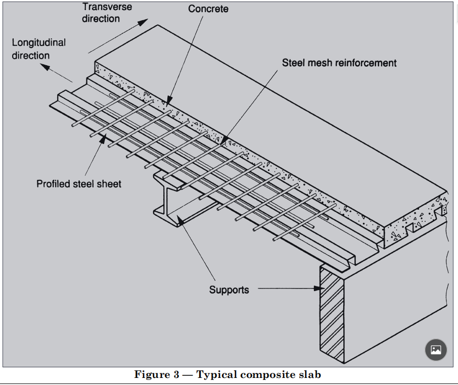
Composite slabs (see Figure 3), should consist of in-situ concrete placed on profiled steel sheets, designed to act as permanent shuttering for the wet concrete, so that as the concrete hardens it will combine structurally with the profiled steel sheets to form a composite element.
Composite action should be obtained in one of the following ways:
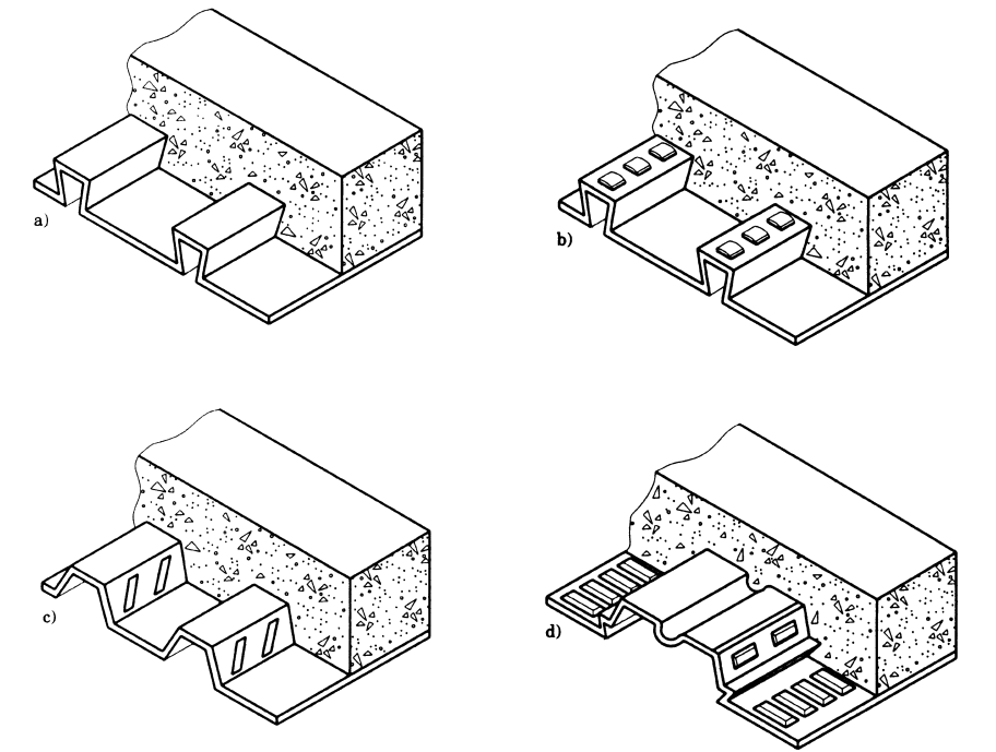
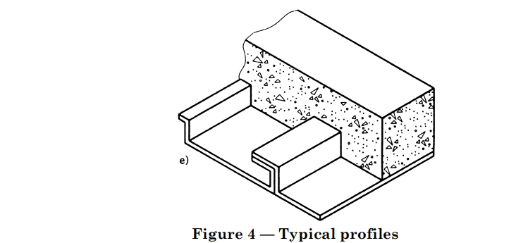
a) by mechanical interlock;
b) by friction induced by the profile shape;
c) by end anchorages;
d) by a combination of c) with either a) or b).
Any bonding or adhesion of a chemical nature should be neglected in design. Steel reinforcement should be provided where necessary (see 4.4). However, steel reinforcement should not be used to resist positive moments in combination with profiled steel sheets, unless the moment capacity has been determined by testing (see 6.3).

Design stages
The following stages should be considered in the design of composite slabs.
a) Stage 1. Profiled steel sheeting as formwork.
The assessment of commercially available shapes of profiled steel sheets, used as formwork to support wet concrete. This includes checking the load carrying capacity, the deflection and the effects of using props (see section 5).
b) Stage 2. Composite slab. Composite action between the profiled steel sheets and the structural concrete slab. This includes checking the load carrying capacity and the deflection (see section 6)
Temporary supports
Normally unpropped construction should be used. However, where safe span limits for construction would otherwise be exceeded, temporary supports should be provided to the profiled steel sheeting until the concrete has reached an adequate strength, in order to avoid exceeding the capacity of the profiled steel sheets under the loading of wet concrete and construction loads. Propped construction should also be used to reduce the deflection of the profiled steel sheeting, where the deflection limits would otherwise be exceeded. Where temporary supports are used, the effects of their use and subsequent removal on the distribution of shear forces in the composite slab should be allowed for in the design of both the supporting and the supported slabs.
NOTE It is essential that temporary supports should be used
only where specified in the design documents or drawings.
The method of providing temporary supports should be chosen to suit the conditions on site. Normally,
one of the following should be used:
a) temporary props from beneath;
b) temporary beams at the soffit of the sheets.
Alternative methods may be used where suitable but, in all cases, the temporary support should be capable of carrying all the loads and forces imposed on it without undue deflection. Where isolated temporary supports are used, a spreader beam should be incorporated in order to provide a continuous support to the profiled steel
sheets. Unless otherwise specified in the design documents or drawings, this should be parallel to the permanent supports.
Regardless of the method of support used, the arrangement should be such that the soffit of the sheet is not cambered above a line joining the level of the permanent supports by a distance greater than Ls /350, where Ls is the effective span of the composite slab. Any slab used to support temporary props should be checked for adequate resistance to the forces applied by the props, or during the removal of the props, using the appropriate concrete strength for the age of that slab.
Provision of reinforcement
Steel reinforcement, in the form of either bars or steel mesh fabric, should be provided in composite
slabs as follows:
a) nominal continuity reinforcement over intermediate supports, for simple spans;
b) full continuity reinforcement over intermediate supports, for continuous spans and for cantilevers;
c) distribution steel, where concentrated loads are applied and around openings;
d) secondary transverse reinforcement to resist shrinkage and temperature stresses.
Where necessary, steel reinforcement should also be provided as follows:
1) to increase the fire resistance of the composite slab;
2) as tensile reinforcement in the span.
e) Reinforcement in the top of the slab should have 25 mm4) nominal cover.
f) Fire resistance reinforcement for negative moment capacity should be placed in the top of the slab with 25 mm4) nominal cover.
g) Secondary transverse reinforcement for controlling shrinkage should be placed in the top of the slab with 25 mm4) nominal cover.
The curtailment and lapping of reinforcement should conform to BS 8110. Where a single layer of reinforcement is used to fulfil more than one of the above purposes, it should satisfy all the relevant recommendations.
NOTE Longitudinal and transverse are used here as defined in 1.3 to describe slab reinforcement. Where a composite slab forms the concrete flange of a composite beam, BS 5950-3.1 gives recommendations for transverse reinforcement of the beam, running perpendicular to the span of the beam. Such reinforcement can be either longitudinal or transverse relative to the slab.


E-mail: info@solidecking.com
tel-phone:86-21-63803633
Address:Room 103, Jinfeng Building, No. 31 Hengfeng Road, Jing'an District, Shanghai
Mobile phone:13816755915 ©2016 Leshang Technologies Co., Ltd.
